In this guide, we will explore how to test a power supply unit using a multimeter.
What is a Power Supply Unit (PSU)?
A power supply unit consists of several components, including transformers, rectifiers, capacitors, and voltage regulators.
Having an adequate number of connectors ensures compatibility with the devices components.
Why Test a Power Supply Unit?
Incorrect voltage or amperage can lead to unstable performance, random shutdowns, or even component damage.
It is the primary tool used for testing a power supply unit.
verify to have a reliable multimeter that can measure both AC and DC voltage and amperage accurately.
It provides an easy and quick way to check the voltage levels and overall functionality of the PSU.
Power supply testers are available in different types, including plug-in testers and digital testers.
It helps simulate the load conditions of the gear to ensure the PSU can handle the required power demands.
Ensure that you have the necessary cables and connectors for accurate testing and measurements.
6.Safety Equipment:Last but not least, safety should always be a priority when working with electrical components.
Some essential safety equipment includes insulated gloves, safety glasses, and a fire extinguisher.
These items will help minimize the risks associated with electrical hazards during the testing process.
It is important to use high-quality, reliable tools to ensure accurate readings and maintain a safe testing environment.
This eliminates the risk of electric shock while handling the components.
These safeguards protect your hands and eyes while handling electrical components.
This is especially important during prolonged testing sessions or when dealing with high-power devices.
Moisture and liquids can damage the components and pose a higher risk of electrical shock.
These tools help dissipate static electricity safely.
Loose or faulty connections can cause inaccurate readings or potential short circuits.
7.Use Proper Tools and Equipment:Use high-quality tools and equipment that are designed for electrical work.
This includes using an appropriately rated multimeter and following the manufacturers instructions for all testing tools.
This can cause electrical shocks or short circuits.
9.Do Not Overload the Power Supply:Be mindful of the power limits of the equipment you are testing.
Overloading the power supply unit can lead to overheating and component failure.
Wait until the machine completely powers down before proceeding.
This severs the electrical connection between the machine and the power source.
3.Locate the Power Supply Unit:Identify the location of the power supply unit within the equipment.
This is usually a rectangular box-shaped component with cables and connectors leading to various parts of the equipment.
4.Unplug the Power Supply Unit:Disconnect the cables and connectors that are connected to the power supply unit.
Take note of the punch in and position of each connector for reassembly later.
To discharge any residual power, press and hold the devices power button for a few seconds.
This helps ensure complete disconnection of the power supply unit.
By following these steps, you have successfully disconnected the power supply unit from the unit.
This preliminary step is crucial to ensure your safety during the testing process.
Remember to handle the power supply unit and its connectors carefully to avoid any damage.
For voltage testing, switch the multimeter to the DC voltage (V) function.
For amperage testing, switch to the DC current (A) function.
Ensure you are using the correct range for the expected values of the power supply unit.
Check the multimeter display to ensure it powers on and is functioning correctly.
4.Connect the Multimeter Probes:Connect the multimeter probes to the corresponding ports on the multimeter.
Connect the probes to a stable power source and verify that the multimeter displays the expected measurements.
This ensures that positive (+) and negative (-) voltages are correctly indicated on the display.
By following these steps, you have properly set up your multimeter for testing the power supply unit.
It is important to double-check that the multimeter is functioning correctly and calibrated to provide accurate readings.
These pins are typically labeled with voltage values, such as +12V, +5V, or +3.3V.
Connect the black probe to the negative (-) voltage pin.
Ensure a secure and stable connection between the probes and the pins.
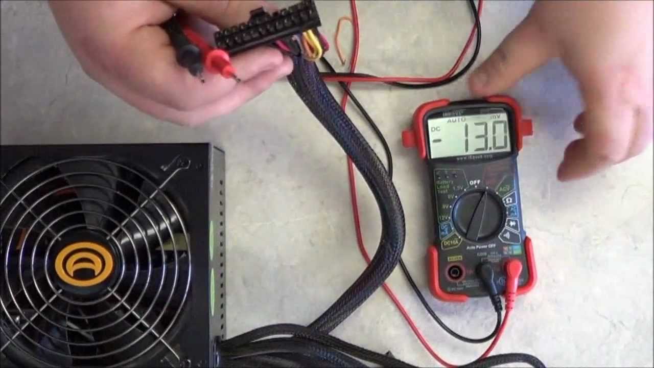
3.Read the Voltage:Once the probes are in place, turn on the power supply unit.
Observe the multimeter display and the voltage measurement it shows.
Note the voltage reading for each tested pin.
Ensure that the measured voltage is within an acceptable range.
Any significant deviations from the specified voltage may indicate a problem with the power supply unit.
This ensures that all voltage outputs are functioning correctly.
6.Document the Results:Record the voltage readings obtained from each tested pin.
Take extra care to avoid accidental contact with other components or cables.
Remember to compare the measured values with the manufacturers specifications to determine if the voltage is within acceptable limits.
These may be labeled with the letter A or I to indicate current.
2.Set the Multimeter to Current Mode:Switch your multimeter to the DC current (A) mode.
Ensure that the multimeter is capable of reading the expected amperage range of the power supply unit.
If necessary, adjust the current range setting to a suitable value.
Ensure that the power supply unit is off and disconnected from the equipment.
This creates a complete circuit for current flow.
Take note of the amperage reading.
Ensure that the measured amperage falls within the expected range.
Any significant deviations may indicate an issue with the power supply units current output.
This helps ensure that all current outputs are functioning correctly.
8.Document the Results:Record the amperage readings obtained from each tested pin or connector.
This documentation will be useful for future reference and comparisons.
Take care to avoid any accidental contact with other components or live circuits.
Testing the amperage helps in identifying any potential issues and ensures the reliable operation of your gear.
look to see if the measured values fall within the acceptable range.
Significant deviations from the specified values may indicate a problem with the power supply unit.
Excessive voltage ripple can cause stability issues in the electronic equipment.
Consult the manufacturers specifications to confirm the allowed voltage ripple.
3.Identify Unusual Readings:Look out for any abnormal or inconsistent readings during the testing process.
Compare this wattage value with the rated wattage provided by the manufacturer.
Ensure that the calculated wattage falls within the rated range.
This may include load testing, efficiency testing, or conducting thermal tests if applicable.
Look for any signs of physical damage or loose connections that may affect the power supply units performance.
They have the expertise and proper tools to diagnose and repair power supply unit problems accurately.
In this guide, we covered the essential steps to test a power supply unit with a multimeter.
We started by disconnecting the power supply unit from the rig and setting up the multimeter for testing.
We then proceeded to test the voltage and amperage, comparing the readings with the manufacturers specifications.
Lastly, we analyzed the readings and performed troubleshooting if necessary.
Regularly testing your PSU is an important maintenance practice to ensure optimal performance and longevity of your electronic devices.
Remember to always prioritize safety when working with electrical components.
